DIY Solar for Beginners: Understand the Parts Before Building
Learn what solar components do, how to match a charge controller to panels and batteries, and how to estimate energy, storage and panel capacity.
Featured Options Compared in This Guide
Full specs & notes ↓Start a DIY solar project with the devices you want to power, their operating hours and when you need them. Daily consumption determines the energy target; simultaneous loads and startup demand determine how much power the system must handle at once.
This primer explains the parts and planning calculations for a small solar project. Use it to develop a component list and discuss a final design with a qualified professional. The examples are planning estimates, not a wiring diagram.
Understand what each component contributes
Panels generate electricity; mounting affects production
Watts describe power, while watt-hours describe energy over time. A panel rated at 200W does not store 200Wh or produce its rated power throughout daylight. Panel ratings use standardized conditions; sunlight, shading and placement affect actual production. University of Maryland Extension explains power, energy and panel sizing.
Choose a usable location before deciding how many panels to buy. Compare shade throughout the day and across seasons, mounting space, orientation and tilt. A spot that is sunny at noon may lose useful morning or afternoon production. Maryland Extension describes shading assessments that reveal these differences.
Temperature also affects output. As solar cells heat up, their voltage generally falls enough to outweigh a smaller increase in current. DOE explains temperature and PV performance.
For a fixed installation, budget for a mounting structure that supports the array and withstands local weather. Mounting is part of the system design, alongside the electrical equipment. DOE: PV system design.
A charge controller manages solar battery charging
A solar charge controller regulates the voltage and current delivered from the panels for battery charging. Its charging controls manage the energy entering the battery to avoid overcharging. Some controllers also have terminals for suitable DC loads. Morningstar identifies PWM, or pulse width modulation, and MPPT, or maximum power point tracking, as controller technologies. Morningstar: how charge controllers work.
An MPPT controller can support a panel array with a higher nominal voltage than the battery and charge that lower-voltage battery within its output limits. Victron describes this behavior for its SmartSolar range. That flexibility still requires checking the input and output separately. Victron: voltage and current ratings.
Use these parameters to select a controller:
| Parameter | What to compare | Practical consequence |
|---|---|---|
| Maximum PV open-circuit voltage, or Voc | The proposed array’s maximum Voc, including the panel temperature coefficient and cold conditions, against the controller’s input ceiling | A panel arrangement acceptable at a warmer temperature can exceed the voltage ceiling in cold weather. |
| PV operating and startup voltage | The array’s voltage against the controller’s required voltage above the battery | Staying below the maximum input voltage alone does not establish that charging can start or continue. |
| Maximum PV short-circuit current, or Isc | The proposed array’s Isc against the controller’s specified input limit | Panel watts alone cannot establish acceptable input current. |
| Battery voltage and output current | The battery bank’s nominal voltage and permitted charging current against the controller’s supported voltages and charge-current setting | A controller must support the bank voltage, and its charging current may need to be reduced for the battery. |
| PV power at the chosen battery voltage | The controller’s power specification and any permitted array oversizing | The same controller can have different PV power figures for different battery voltages; extra panel power may be limited. |
These checks follow Victron’s installation requirements, technical specifications and battery settings. Their numerical limits apply to the models covered by that manual.
For a concrete comparison, Victron lists its 75/15 with a 75V maximum PV input and a 15A maximum battery charge current. Its 100/15 raises the PV voltage ceiling to 100V while retaining the same 15A charging limit. Both support 12V and 24V batteries. Moving between these models therefore changes the permitted input voltage without increasing maximum charging current. Victron: model ratings.
The operating requirements add another constraint: for this controller family, PV voltage must exceed battery voltage by 5V to start charging, then remain at least 1V above it during operation. These are model-specific thresholds, not universal rules for solar controllers. The specifications also state that excess PV power is limited; that does not waive the separate voltage and short-circuit-current limits. Victron: specifications and footnotes.
Battery chemistry determines the charging settings. Match the charge profile to the battery manufacturer’s requirements, including charging voltage, current, absorption duration, float behavior and temperature provisions. Victron allows charge-current reduction for smaller banks and warns that equalization can damage unsuitable batteries; its lithium preset does not offer equalization. Victron: charging configuration.
For a battery that may get cold, establish how charging will be stopped below its permitted temperature. In this Victron family, the configurable low-temperature cutoff is disabled by default and requires battery-temperature data through a VE.Smart network. Selecting a lithium preset alone does not establish that this cutoff is operating. Victron: temperature settings.
Write down the intended panel arrangement, battery voltage and charging requirements before purchasing. If you expect to add panels later, assess the expanded arrangement against all of these limits.
Batteries address timing; inverters supply AC
A battery stores energy for nighttime or periods of reduced sunlight. An inverter converts DC electricity to AC for AC appliances. Identify which loads need AC and which can use a suitable DC supply before choosing equipment. DOE: storage and inverters.
For inverter sizing, record the loads that may run together and any motor startup demand. A refrigerator or pump needs more consideration than its daily watt-hour total alone. Maryland Extension: load assessment.
A controller’s load terminals are not automatically an appropriate inverter supply. Morningstar’s AC-system example powers the inverter from the battery because startup current can exceed the controller’s load-terminal capacity. That battery connection still needs appropriately designed wiring and protection. Morningstar: AC-load arrangement.
Larger inverters can draw substantial battery current. As an illustration, assume a 2,000W AC load, a constant 12V DC input and 90% inverter efficiency:
DC current = 2,000 ÷ 12 ÷ 0.90 ≈ 185A.
These are assumptions, not measured equipment performance. Victron explains that increasing system voltage reduces DC current for a given power demand, making voltage a consequential design choice before ordering the battery, inverter and cables. Victron: DC cable selection.
Turn a load list into an energy budget
For each device, record its power and intended operating hours. Multiply watts by hours to estimate watt-hours, then add the loads. Record simultaneous operation and startup demand separately. Maryland Extension recommends this itemized approach for off-grid and battery-integrated systems. Maryland Extension: load assessment.
Here is a hypothetical worksheet. The values represent assumed constant loads, not appliance measurements:
| Assumed load | Power | Daily operating time | Daily energy |
|---|---|---|---|
| Load A | 40W | 5 hours | 200Wh |
| Load B | 50W | 6 hours | 300Wh |
| Load C | 10W | 10 hours | 100Wh |
| Total | 600Wh |
If all three operate together, their running demand is 100W. Their daily consumption is 600Wh. Use the first figure when considering simultaneous power and the second when planning generation and storage.
Before increasing system size, consider reducing operating hours or removing optional loads. Maryland Extension recommends conservation and efficiency measures before investing in additional solar capacity.
Set a storage target
At 600Wh per day, two days without solar require 1,200Wh delivered to the loads.
For illustration, suppose 80% of a starting stored-energy amount is allocated for use, and 90% of that allocated energy reaches the loads:
Starting stored energy = 1,200 ÷ 0.80 ÷ 0.90 ≈ 1,667Wh.
The percentages are hypothetical allowances, not battery specifications or recommended settings. The example shows why delivered energy and nominal storage are different planning quantities. The actual battery’s operating limits and the system’s losses determine the applicable values. DOE describes storage’s role in supplying energy when sunlight is unavailable. DOE: battery storage.
Connect daily consumption to panel capacity
Peak sun hours measure equivalent hours of sunlight at 1,000W per square meter. They differ from the hours between sunrise and sunset. Use solar-resource estimates for your location and operating season. Maryland Extension explains both peak sun hours and seasonal variation. Maryland Extension: solar resource and sizing.
Applying its energy-balance approach over a daily planning period:
Estimated panel watts = daily energy target ÷ peak sun hours ÷ derate factor.
The derate factor accounts for losses. For the following hypothetical examples, assume a 600Wh daily target and a factor of 0.75 for the complete energy path to the loads:
| Assumed solar resource | Calculated array capacity | Quantity using hypothetical 200W panels |
|---|---|---|
| 3 peak sun hours per day | 600 ÷ 3 ÷ 0.75 ≈ 267W | 2 panels, totaling 400W |
| 1.5 peak sun hours per day | 600 ÷ 1.5 ÷ 0.75 ≈ 533W | 3 panels, totaling 600W |
These are scenarios, not local sunshine estimates or equipment recommendations. The loss factor must reflect the actual system. Panel counts are rounded up using Maryland Extension’s method; they do not specify an electrically compatible panel arrangement.
For summer-only use, assess the months the system will operate. For year-round use, compare monthly consumption with monthly production. An annual average can conceal a seasonal shortfall. Maryland Extension discusses seasonal demand and monthly production estimates in its sizing guidance.
Also distinguish ordinary daily consumption from recovery after cloudy weather. Replenishing depleted storage while running the loads requires energy beyond that day’s consumption. If the required array will not fit your site, revise the loads or operating expectations. A larger battery can store more energy, but it cannot generate the energy needed to refill it.
Budget for wiring, connectors and protection
Sketch the physical layout before ordering cables. Include both positive and negative cable lengths: current, conductor cross-section and cable length affect voltage drop and heating. Use equipment-specific cable and fuse requirements when developing the design. Victron: DC wiring.
Three purchasing decisions deserve particular attention:
- Fuses need more than an amp rating. Match their current rating, DC voltage rating, interrupt capability and operating characteristics to the circuit. Interrupt capability is the fault current a fuse can interrupt; lithium batteries can supply very high short-circuit currents. Victron: fuses and interrupt ratings.
- A disconnect must suit its intended operation. Some isolation switches cannot interrupt DC current under load. Specify the expected current, voltage and switching duty. Victron: DC isolation switches.
- PV connectors need an identified mating pair. Stäubli warns against mating connectors from different manufacturers and explains that certification applies to specified product-family combinations. Physical fit or an advertised compatibility claim does not establish an approved pairing. Stäubli: connector cross-connections.
For rooftop or grid-connected work, involve a qualified installer and establish local requirements before installation. DOE describes permitting, inspection and utility connection as steps preceding grid operation, with requirements varying by jurisdiction. DOE: rooftop permitting and inspection.
Before ordering, assemble a load worksheet, seasonal production estimate, storage target, controller compatibility comparison and component-specific wiring and protection plan. Maryland Extension recommends qualified professional input for final design decisions. For related buying considerations, see the solar panel kit budget guide or portable power station guide.
Sources
- Department of Energy: Solar Photovoltaic System Design Basics
- Department of Energy: Solar Photovoltaic Performance and Efficiency Basics
- University of Maryland Extension: Working on Solar Design and System Sizing
- Morningstar: How Does a Solar Charge Controller Work?
- Victron Energy: SmartSolar MPPT—Introduction and Ratings
- Victron Energy: SmartSolar MPPT—Installation
- Victron Energy: SmartSolar MPPT—Technical Specifications
- Victron Energy: SmartSolar MPPT—Configuration and Settings
- Victron Energy: Wiring Unlimited—DC Wiring
- Stäubli: PV Connector Cross-Connections
- Department of Energy: Permitting and Inspection for Rooftop Solar
Products Compared in This Guide
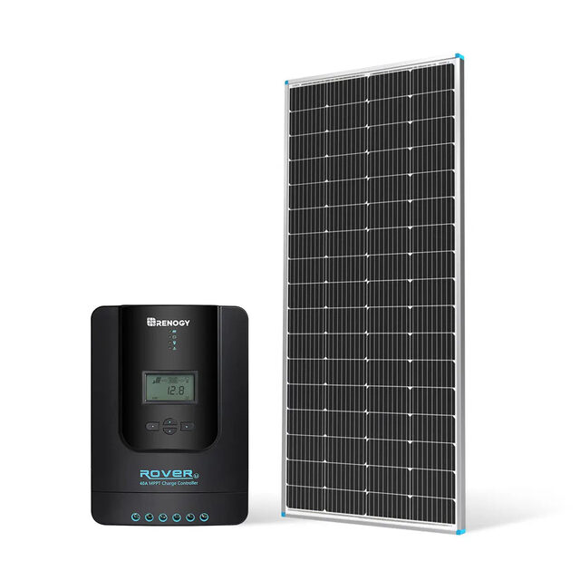
Renogy 200W 12V Monocrystalline Solar Panel
The starting point for any DIY solar build. 200W mono, 25-year warranty, pre-drilled mounting holes, MC4 connectors. Buy one to start; add more as your system grows.
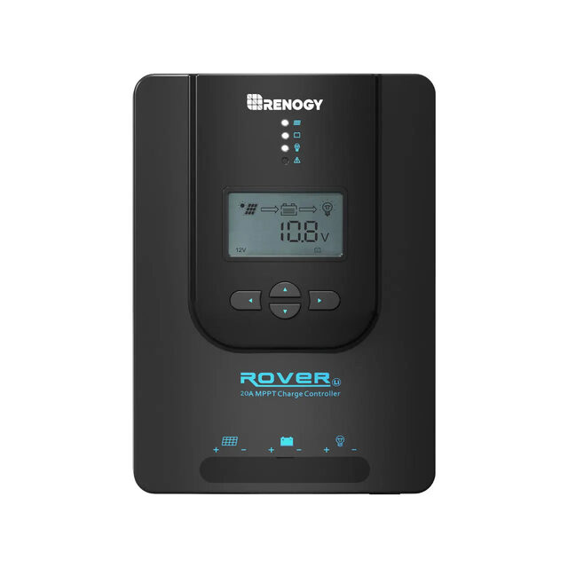
Renogy Rover 20A MPPT Solar Charge Controller
The right MPPT controller for a 200–260W system at 12V. Add the Renogy BT-1 Bluetooth module ($25) for phone monitoring. Handles 12V or 24V battery banks.
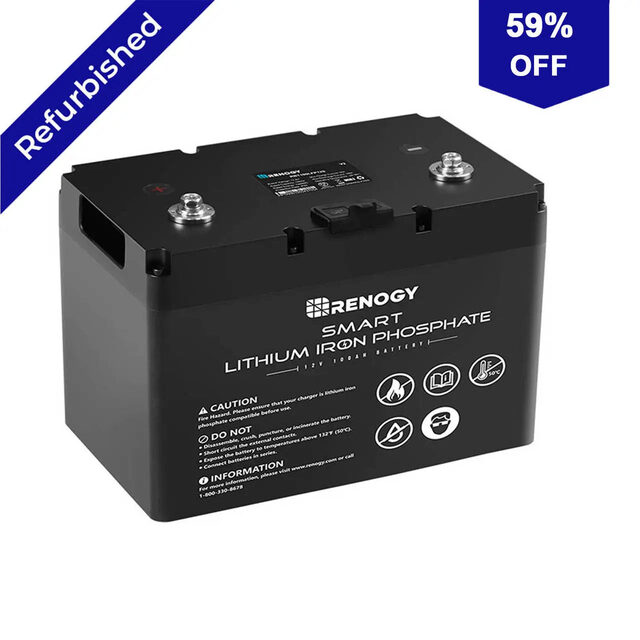
Renogy Smart Lithium Iron Phosphate 100Ah 12V Battery
Renogy's own LiFePO4 battery—lower cost than Battle Born but with similar specs (100Ah, built-in BMS, 2,000+ cycle rating). The right starting battery for a budget DIY build.
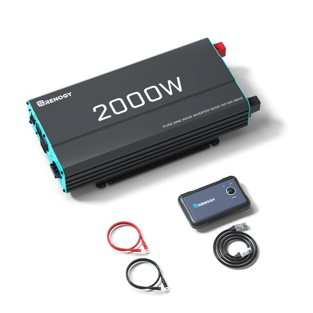
Renogy 2000W Pure Sine Wave Inverter
Converts 12V battery DC to 120V AC household power. 2,000W continuous, 4,000W peak surge. Handles most household loads. Add a transfer switch for home backup use.
Frequently Asked Questions
What does a solar charge controller do?
It regulates voltage and current from solar panels for battery charging. Selection depends on panel input voltage and current limits, supported battery voltage, charging current and a charge profile suited to the battery.
What do an inverter and battery do in a solar system?
An inverter converts DC electricity to AC for AC loads. A battery stores energy for later use, including nighttime or cloudy periods.
Is a 12V battery system safe just because its voltage is low?
Low voltage does not eliminate high battery fault currents. Wiring and protection must account for operating current, cable length, DC voltage and available short-circuit current.
Can daily energy use tell me how many panels to buy?
It provides a starting estimate when combined with local peak sun hours and a factor for system losses. The result does not establish electrical compatibility or guarantee power through cloudy weather.